Product Overview
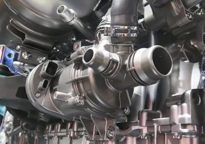
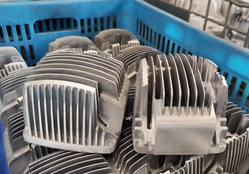
Aluminum die casting power electronic module housings are critical structural components designed to protect sensitive electronic systems and ensure efficient heat dissipation in high-power electrical applications. These housings are widely used in power converters, inverters, motor drives, and industrial control equipment.
Manufactured through high-precision aluminum die casting combined with CNC machining, the housing provides excellent dimensional stability, high thermal conductivity, and strong mechanical strength. The lightweight aluminum alloy structure also offers excellent corrosion resistance and durability, making it suitable for demanding industrial environments.
Our custom aluminum die casting solutions allow flexible design optimization to meet the requirements of complex electronic modules while maintaining high production efficiency and consistent quality.
Material Options
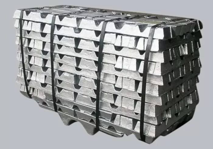
Power electronic module housings are typically manufactured using high-performance aluminum alloys that provide excellent heat dissipation, structural strength, and corrosion resistance.
Common material options include:
-
ADC12 Aluminum Alloy – Excellent casting performance and cost efficiency.
-
A380 Aluminum Alloy – High strength with good thermal conductivity, suitable for electronic and automotive components.
-
AlSi10Mg Aluminum Alloy – Provides superior mechanical properties and improved durability.
-
AlSi9Cu3 Aluminum Alloy – Widely used for precision die casting electronic housings.
Applications
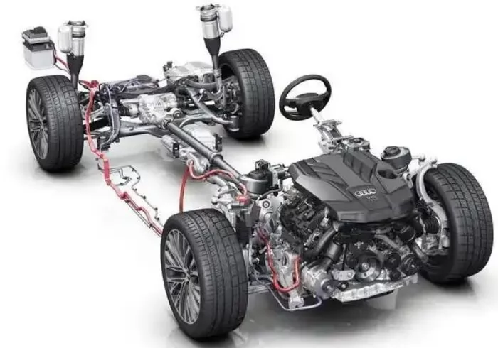
Aluminum die casting power electronic module housings are widely used in industries that require reliable protection and effective heat management for electronic systems.
Typical applications include:
-
Electric vehicle power inverters
-
Industrial motor drive systems
-
Renewable energy converters
-
Power supply modules
-
Industrial automation equipment
-
Energy storage systems
-
High-power electronic control units
Key Advantages
Our aluminum die casting power electronic module housings offer several important advantages for high-performance electronic applications:
-
Excellent heat dissipation performance to support high-power electronic modules.
-
High dimensional accuracy achieved through precision die casting and CNC machining.
-
Lightweight aluminum alloy structure with strong mechanical strength.
-
Good corrosion resistance and long service life in industrial environments.
-
Suitable for complex structural designs and integrated housing solutions.
-
Stable mass production capability supported by strict quality control systems.
These advantages make aluminum die casting an ideal manufacturing solution for power electronic module housings used in demanding industrial applications.
Project Brief
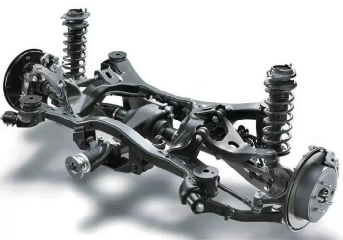
This is a customized agricultural machinery component, applied in equipment such as corn harvesters and tractors.
1. Product Standards & Requirements: Material: AISi6Cu4Zn; Dimensional tolerance class: ISO 8062-CT8; Minimum dimensional tolerance: ±0.1 mm; Surface free of visible defects; Surface roughness: Ra6.3µmµm; PPAP approval must be completed and passed before mass production.
2. Product Challenges: The component features a completely rotational structure, which places high demands on the gating system design. During machining, fixtures cannot achieve physical error-proofing. Additionally, the part contains multiple tubular holes, which are prone to forming air stagnation zones.
The finished product must not only demonstrate excellent machining accuracy and surface finish, but also provide high thermal conductivity, corrosion resistance, lightweight design, and ease of installation and maintenance. Overall, this project presents a certain level of difficulty, posing a comprehensive test of our mold design capability, machining capability, quality control, and delivery performance.
Development Process
1. Following the Advanced Product Quality Planning (APQP) process, we established a project development team consisting of a mold designer, casting engineer, machining engineer, measurement engineer, quality engineer, and sales engineer, ensuring a quality-centered approach throughout the entire product development cycle.
2. Through DFM analysis, we optimized some structural details of the product to enhance manufacturability, and established mutually agreed technical specifications and quality standards with the customer.
3. Based on material characteristics and the core design elements of this product, considering technical feasibility, quality stability, and cost control, we ultimately selected the process route of gravity casting + CNC precision machining.
4. Technical engineers conducted mold design reviews, mold design and simulation, and flow analysis to predict and optimize key challenges and process parameters, providing the customer with a die-casting simulation analysis report.
5. In the subsequent practical stages, we gradually verified the solution, identified issues, and implemented improvements as follows:
• Issue: X-ray inspection after mold trials revealed local porosity exceeding acceptable limits.
- Solution: Redesigned the threaded holes into pin structures to eliminate porosity.
• Issue: Due to the fully rotational structure, fixtures could not physically prevent incorrect orientation during machining.
- Solution: Enhanced the work instruction documentation to ensure clear and accurate descriptions and added directional arrow markings on the casting blanks to guide correct positioning.
A complete inspection process was implemented, including first article inspection, in-process inspection, and final inspection before shipment, with full data recording and traceability to ensure all quality data are verifiable.
Meanwhile, during development, we established standardized documentation such as FMEA, SPC, MSA, and Process Control Plans, ultimately completing the PPAP documentation, which was approved by the customer.
The finished aluminum die-cast agricultural machinery component demonstrates excellent performance and precision, along with outstanding thermal conductivity, corrosion resistance, lightweight construction, and protective properties. It is also easy to install and maintain. The final product fully achieved the customer’s design goals, providing a higher-performance and more reliable solution for similar component designs.
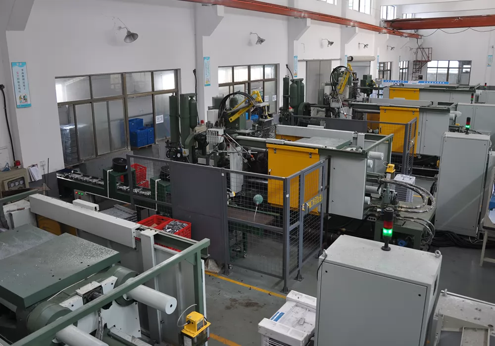
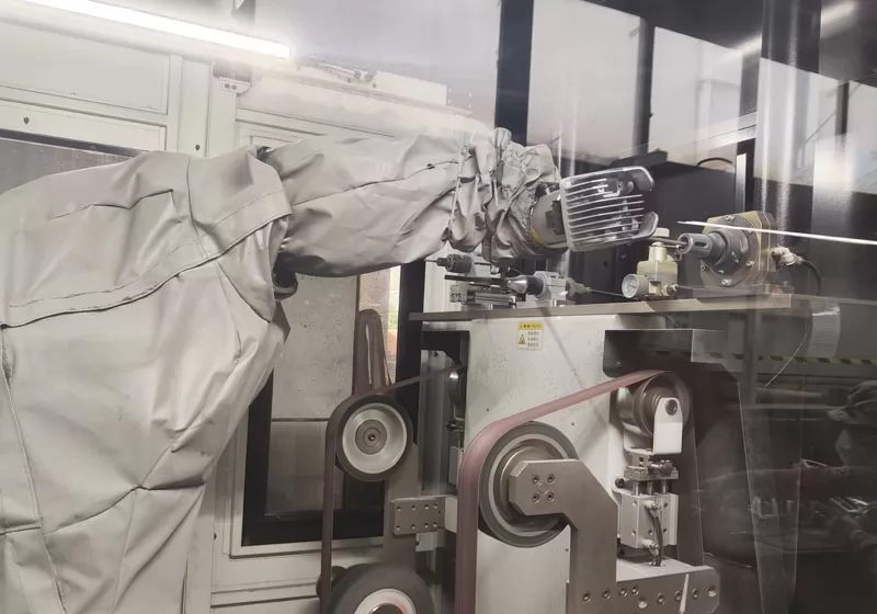
Production Process
Mould making→High Pressure Die Casting→Cutting the sprue and riser→Polishing→Deburring→CNC Machining→Powder coating→Reaming→Packaging & inspection
FAQs
Q1. How to get a quote?
We ask for 3D models or detailed 2D drawings. Samples may also be provided for pricing purposes. Please also provide specific details such as the product quantity, annual demand, raw materials, and dimensional tolerances. We accept 3D models in .PRT and .SLDPRT formats, as well as neutral formats such as .IGS, .STP, and .X_T.
Q2. What is the minimum order quantity for the product?
Q3. How long does it usually take to deliver the product?
Because the customer's product demand and complexity is different, need to use different die-casting or casting process, so the delivery time is not the same, we will be with the customer before booking the contract for delivery time confirmation. tooling lead time: 5-8weeks according to different parts; first samples lead time: 1-3weeks after tooling ready. mass order lead time: 5-7weeks
Q4. How to ensure quality?
we will use 8D tool to process customer's complaint, define root cause and improvment actions.