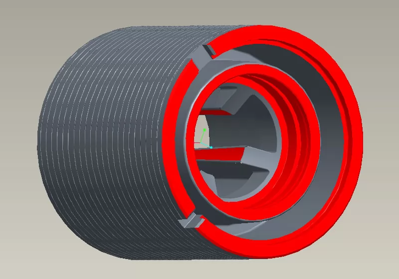
This is a custom-designed motor stator tube casting. The product features a hollow cylindrical structure with double-layer concentric coaxial sleeves, presenting complex internal and external geometries.
1. Product Standards & Requirements: Material: ADC12; General dimensional tolerance grade: ISO 8062-CT3; Special positional dimensional tolerance minimum: 0.01; Flawless appearance (no visible defects); Surface roughness: Ra0.8µm; Porosity standard reference: ISO 10049. PPAP approval must be completed and passed before formal mass production.
2. Product Challenges: The product wall thickness ranges from 4mm to 9mm, making it prone to porosity issues. The structure is susceptible to short shots during die-casting, with a tendency for thick flash in the middle section. The surface must be very smooth, assembly accuracy requirements are very high, and it demands high precision CNC machining.
Risk Keywords: Complex structure, High precision, Surface quality, Assembly accuracy, Zero appearance defects
The finished product must possess excellent machining precision and surface finish, along with good thermal conductivity, corrosion resistance, and lightweight characteristics, while also being easy to install and maintain. The overall project is challenging, particularly testing our capabilities in mold design, quality control, and delivery.
Development Process
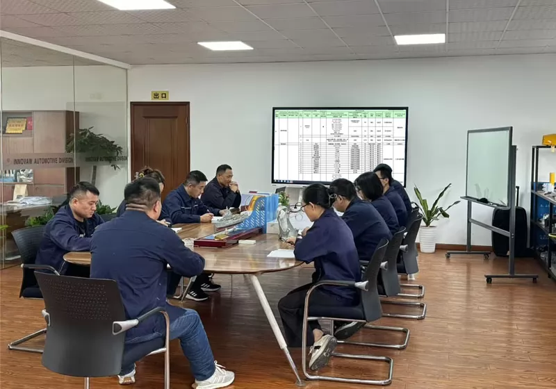
Following the core methodology of the internationally advanced IATF 16949 standard - Advanced Product Quality Planning (APQP), we formed a project development team comprising mold designers, casting engineers, machining engineers, measurement engineers, quality engineers, and sales. Focusing on quality, we entered the comprehensive product development process.
The first step involved DFM analysis to thoroughly understand and optimize certain product details for enhanced manufacturability, establishing mutually agreed-upon technical specifications and quality standards with the customer.
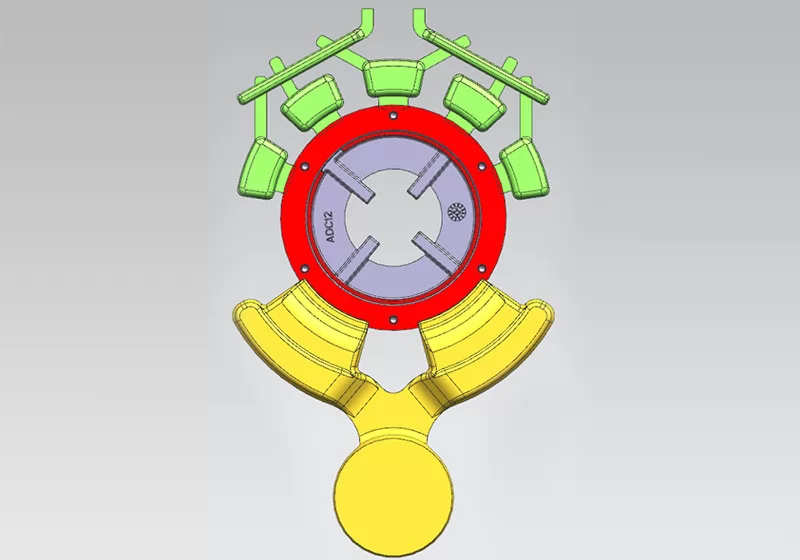
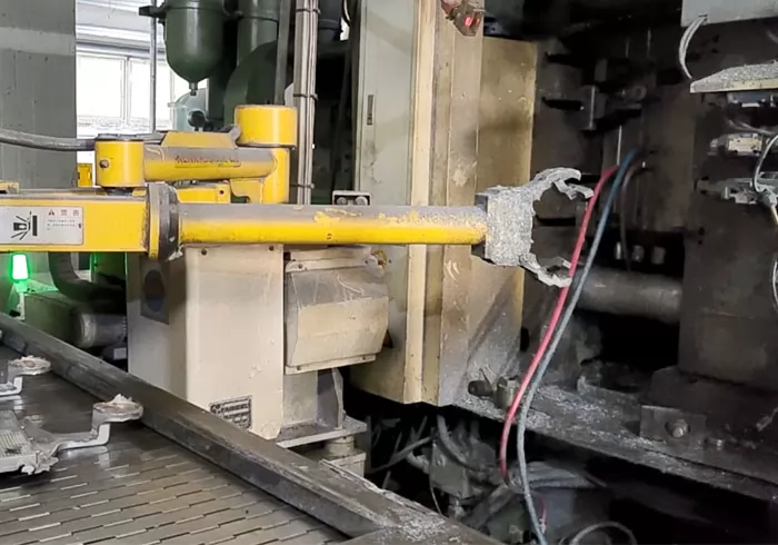
Considering the application environment and performance requirements of this motor stator tube, the housing material was confirmed as ADC12 aluminum alloy. Based on the material properties and the core design elements of the product, the process route of high-pressure die casting (HPDC) + CNC precision machining was ultimately determined, balancing technical feasibility, quality stability, and cost control.
Subsequently, technical engineers performed mold simulation and mold flow analysis to predict and optimize various challenges and process parameters, and established preliminary Process Flow Charts and Control Plans.
Finally, the plan was gradually validated, and issues were identified and resolved in the subsequent practical stages.
Practice Validation & Optimization
Starting from mold manufacturing, the project entered the actual production phase. Our company proceeded according to the initial Process Flow Chart, established the Control Plan, and applied FMEA tools for risk analysis and assessment of various potential failure modes. The main key issues encountered during the actual manufacturing process were as follows:
A. Optimizing Mold to Solve Porosity Issues
This motor stator tube casting has relatively thick walls, making it prone to porosity issues under high-pressure die casting conditions. Beyond referencing ISO 10049, the customer specified stricter porosity standards for several special dimensions. During the trial mold phase, quality engineers identified porosity issues through X-ray inspection. The team conducted technical reviews, investigated the pattern of porosity distribution, and defined the solution:
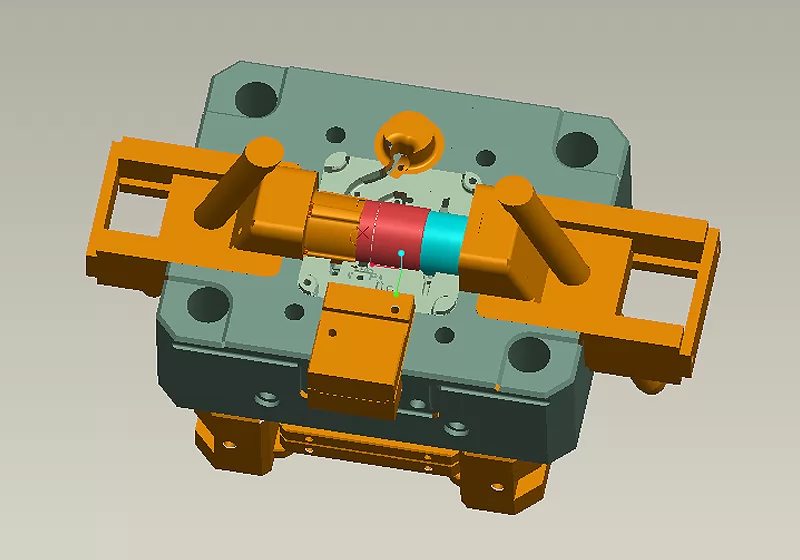
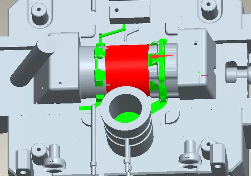
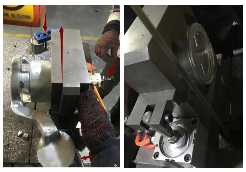
1. Changed the mold gate location from the center to the end face, allowing smoother material flow and more efficient venting of gases.
2. Adjusted and precisely controlled die-casting parameters, applying Statistical Process Control (SPC) to core parameter data. Data from each batch was collected into the system and analyzed using SPC tools for continuous monitoring and improvement.
After validation through X-ray inspection of multiple sample batches, the porosity rate met customer requirements, achieving a 100% pass rate.
B. Resolving Short Shot Issues
During the trial mold phase, feedback indicated short shots in some areas, primarily concentrated in the middle of the housing and at seam locations. Through technical investigation and optimization, including numerical simulation and practical comparison of the mold feeding system, insufficient flow velocity of molten metal in local areas was confirmed. We adjusted pressure parameters and the metal filling path, increasing flow velocity to enhance local filling capability. After optimization, multiple trial runs confirmed the short shot issue was effectively resolved.
C. Flash Thickening Issue
During the same trial-molding stage, engineers observed that the central area of the motor stator tube casting was prone to thick flash, which increased the difficulty of removal and negatively affected subsequent operations and efficiency. To address this, the development team specifically designed and implemented a dedicated punching device to remove the excessive flash through post-process stamping, ensuring both the appearance and dimensional accuracy met customer requirements while maintaining production efficiency.
D. Temperature Compensation Optimizes Machining Dimensional Deviation
The product requires extremely strict dimensional tolerance control. During the CNC machining stage, inspection engineers detected fluctuations in the dimensional accuracy of some product features, with tolerances exceeding limits. The technical team conducted an on-site investigation and utilized SPC tools to systematically collect, organize, and analyze historical production process data, identifying variation patterns and potential abnormal trends in key process parameters. The conclusion was that different ambient temperatures caused machining dimensional shifts, affecting yield. Addressing this phenomenon and considering production efficiency, the technical team defined the following temperature compensation improvement strategy:
1. Identified two key temperature nodes: 28°C and 8°C.
2. Added instructions to CNC operating points regarding the effect of temperature on key dimensions and specific control methods: For dimensions with tight tolerances, when producing at room temperatures above 28°C, control the product dimension towards the upper middle of the tolerance band; when producing below 8°C, control it towards the lower middle. After implementing the temperature compensation strategy, inspection engineers confirmed through multiple batch checks that tolerances remained within normal and acceptable levels, successfully resolving the issue.
Quality Control
The entire development process was a systematic procedure of identifying and controlling quality risks while continuously optimizing the process. The motor stator tube project team leveraged rich experience and solid technology to conduct technical reviews and repeated verification at every process step, systematically identifying and tackling potential risk points. The team's quality engineers strictly adhered to the IATF 16949 quality system, implementing the full APQP process requirements to achieve full-process quality control. Throughout the process, various standardized documents and practices such as FMEA, SPC, MSA, and Control Plans were established and executed to prevent potential process risks, quality risks, and control quality variation. Finally, PPAP documentation was established and approved by the customer, laying a solid foundation for formal mass production.
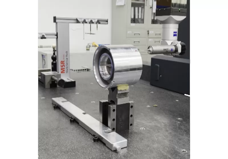
The process included first-article inspection, in-process inspection, and outgoing inspection, establishing complete inspection data retention to ensure all quality data is traceable and verifiable.
Results and Evaluation
Finished Product Metrics:
1. Dimensional Accuracy: Including indicators like flatness and perpendicularity, all met standards.
2. Surface Quality: Roughness Ra0.8µm, standard met.
3. PPAP completed and approved by the customer.
The development of this aluminum die-cast motor stator tube project by Innovaw, characterized by its relatively high technical difficulty and stringent comprehensive performance requirements, served as a test of the manufacturer's overall capabilities. Relying on our profound expertise in high-pressure die casting, precision CNC machining capabilities, and an excellent quality management system consistently implemented throughout the process, we successfully overcame the challenges and delivered a high-quality product that met and even exceeded customer expectations. This fully demonstrates our casting development team's professional capability for systematic problem analysis and rapid closed-loop improvement in developing complex structural components.
Production Process
Mould making→Melting→High Pressure Die Casting→Cutting the sprue and riser→Deburring→Shot Blasting→Machinine 1→Machinine 2→Machinine 2→Clean→Packaging & inspection
Production Show
FAQs
Q1. How to get a quote?
We ask for 3D models or detailed 2D drawings. Samples may also be provided for pricing purposes. Please also provide specific details such as the product quantity, annual demand, raw materials, and dimensional tolerances. We accept 3D models in .PRT and .SLDPRT formats, as well as neutral formats such as .IGS, .STP, and .X_T.
Q2. What is the minimum order quantity for the product?
100
Q3. How long does it usually take to deliver the product?
Because the customer's product demand and complexity is different, need to use different die-casting or casting process, so the delivery time is not the same, we will be with the customer before booking the contract for delivery time confirmation. tooling lead time: 5-8weeks according to different parts; first samples lead time: 1-3weeks after tooling ready. mass order lead time: 5-7weeks
Q4. How to ensure quality?
we will use 8D tool to process customer's complaint, define root cause and improvment actions.
0
Comments
Share your thoughts
Showing
6
of
0
reviews
Leave a Comment
Your email address will not be published. Required fields are marked *
Click on a star to rate it ! (Average rating 5 / 5. Vote count: 44)